

Match to Live Action
VFX Lighting Process
For this project we’re trying to match a CG model and lighting to its real-world counterpart. The harder it is to tell which object is real, the better you’ve done!
Start out by choosing an object. For this particular iteration of the project, we are focusing on bounce light and color, so make sure and choose an object that either gives off or receives bounce light very well. Also, try and choose an object that’s fairly quick and easy to model; this project is about the lighting and integration, not primo modeling skills, and the more complex the object, the more ways the CG could differ from the real, making it easier to tell the two apart. Originally, I was planning on trying to recreate dungeons & dragons dice because of all the fun colors and to show off a little personality, but they turned out to be too small and reflective to effectively give off or receive bounce color, so I opted instead for an egg. Eggs show bounce light like champs, and are also very simple to model.
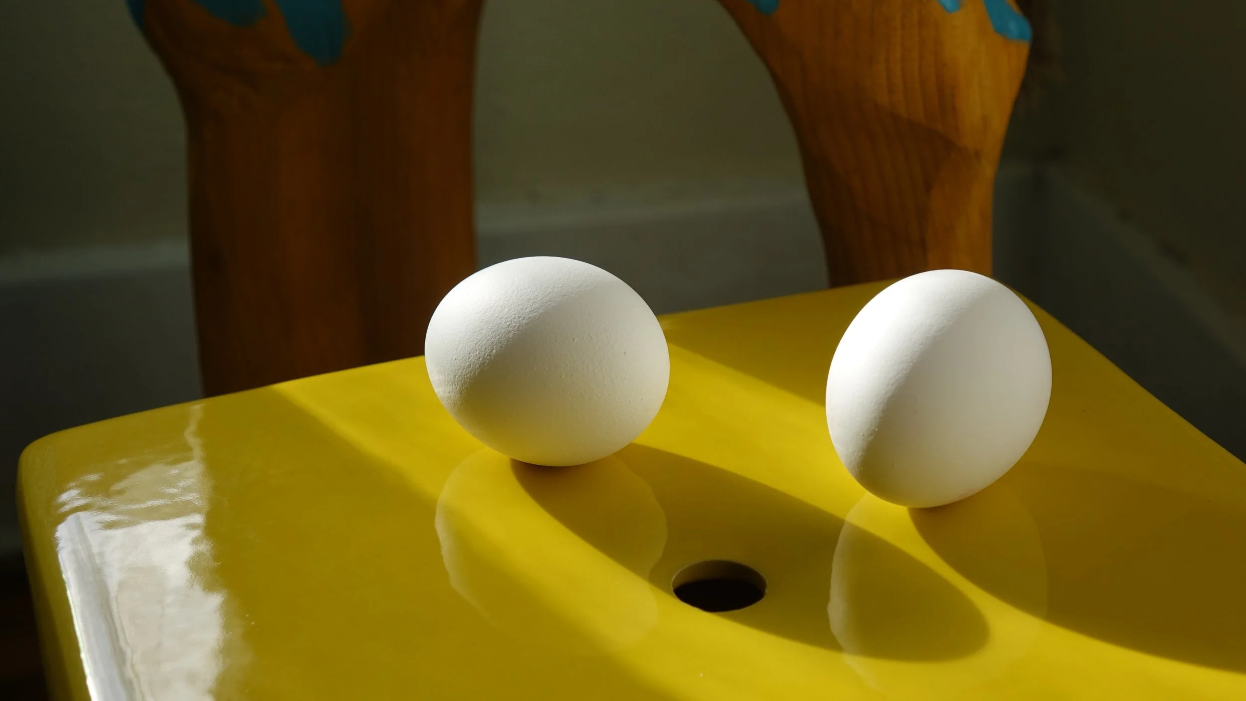


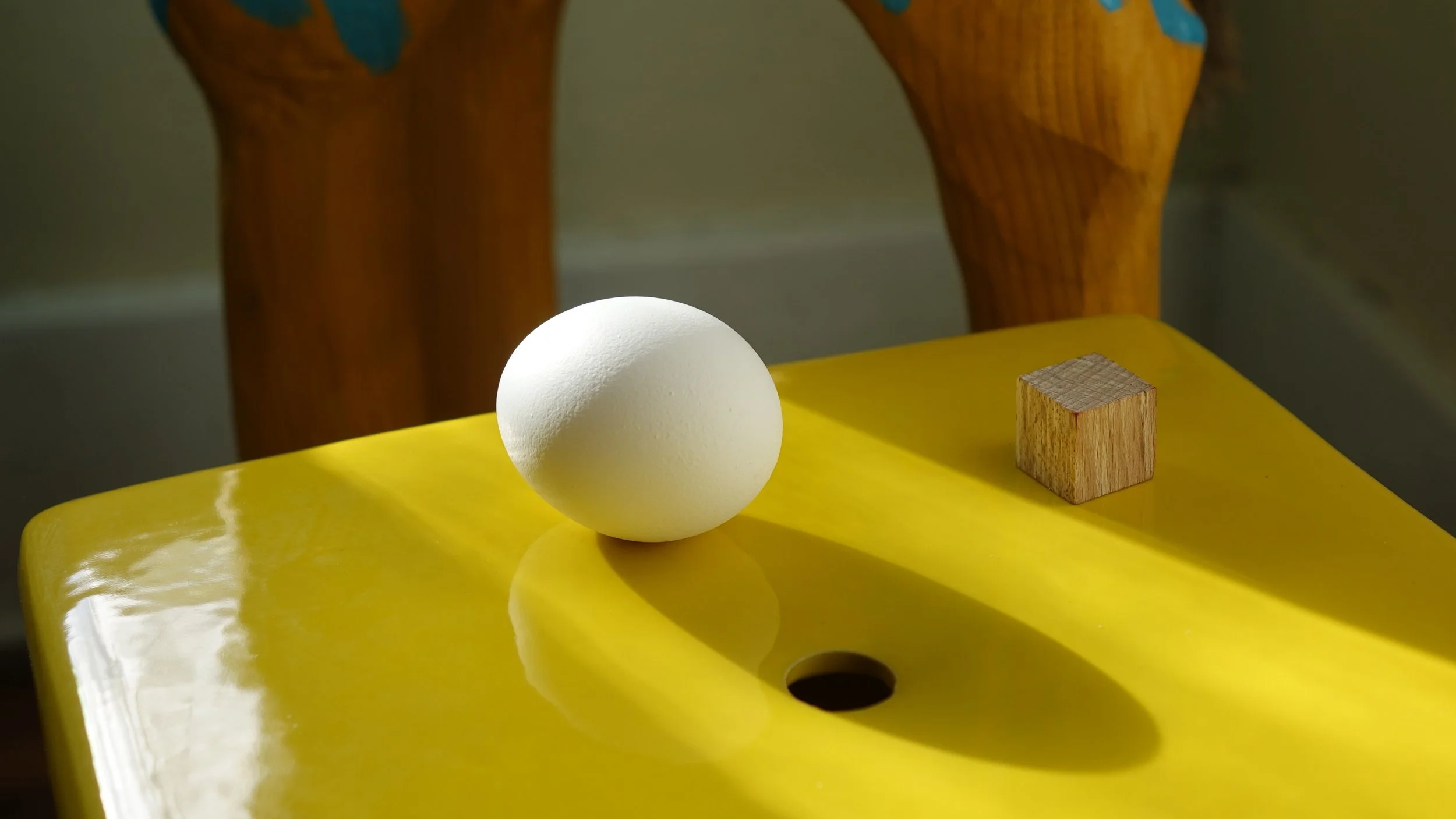
Now that you have an object picked out, take photos of it. While any camera will do, nicer, professional photography cameras work the best, and will give you the most control over how your photos look, as well as giving you the resolution you need to work with. Through my school I ended up with a Sony DSC-RX10M2. However, even a point and shoot camera would work if that’s all you have available. You’ll also need a light integration kit which consists of a diffuse sphere, a chrome sphere, and a diffuse cube. You can make your own by buying a wooden ball and cube and a reflective, decorative sphere for significantly cheaper than buying the professional grade stuff, and it will still give you good results. For the egg, I used a 1 inch light integration kit (as opposed to 4 or 6) as all of the objects were more similar in size to the egg. Side tip: if you end up using an egg, hard boil it first; it’ll be less translucent and will also make less mess if cracked and later on when you need modeling reference. Now that you have your tools, make sure to do proper set up for your photos. You want to make sure that you have strong shadows and less light sources will make it easier later on. You also need to make sure that you’re getting strong bounce. For me, it meant placing my egg on or near surfaces that were brightly colored. For each environment set up, you want to take 5 photos: A blank slate photo with just the environment; a photo with the egg; and one a piece for each of the light integration kit objects (cube, sphere, chrome), where the objects are sitting where the egg was in the previous photo. Make sure the settings on the camera stay the same for each photo in the set. I ended up doing 5 sets photos with 5 different lighting set ups, and ultimately went with the one with the best mix of interesting composition and good bounce color.
There’s more thing before starting lighting that you need, and that’s the model! The model, and its texture, need to be as accurate as possible, so make sure to have plenty of reference, and even scan the object if you can. For the egg, I scanned it, and then cut it in half and scanned it again so I had good reference photos of the actual shape. If you object has a label, try and peel it off and scan that as well so you have a texture ready to go. Now, we’re ready to start the lighting process!
Photo Metadata
We’re going to start out the lighting in Autodesk Maya by making sure that the 3D camera, we’ll call this the RenderCam, matches the real life camera as much as possible. That means looking at the metadata of the photos you took in order to obtain camera type, focal length, and resolution. The RenderCam render settings need to be in the same ratio as the camera resolution, though not as big so render times don’t take too long. For example, my real camera’s resolution was 5472 by 3080, and I wanted something with the same ratio around the normal 1280 by 720, and it ended up at 1280 by 721. To get the correct number to plug into the RenderCam focal length, you have to find the crop factor of the camera you used and multiply it by the focal length shown in the metadata of the image. You can do this googling the camera type you used and crop factor, i.e. “Sony DSC-RX10M2 crop factor.” Mine was 2.73 and the focal length was 23 mm, giving me a Maya focal length of 62.79. If you can’t find the crop factor, then find the sensor size and plug the information into www.digified.net/focallength and it will do the calculation for you. Once you find the new focal length number, plug it into the RenderCam focal length and your camera should match. The last thing you need to do to get your scene ready is make sure that the scale in Maya’s 3D space will match the real world, meaning you have to set the scale of your scene to inches (or whatever unit of measurement you’re using; for mine it was inches). You can do this by going to Windows > settings/preferences > preferences > settings, and then using the drop down menu of linear working units and choosing inches. Now we’re ready to start matching to our images!
Cube in alignment with photo
Egg with shadow in position
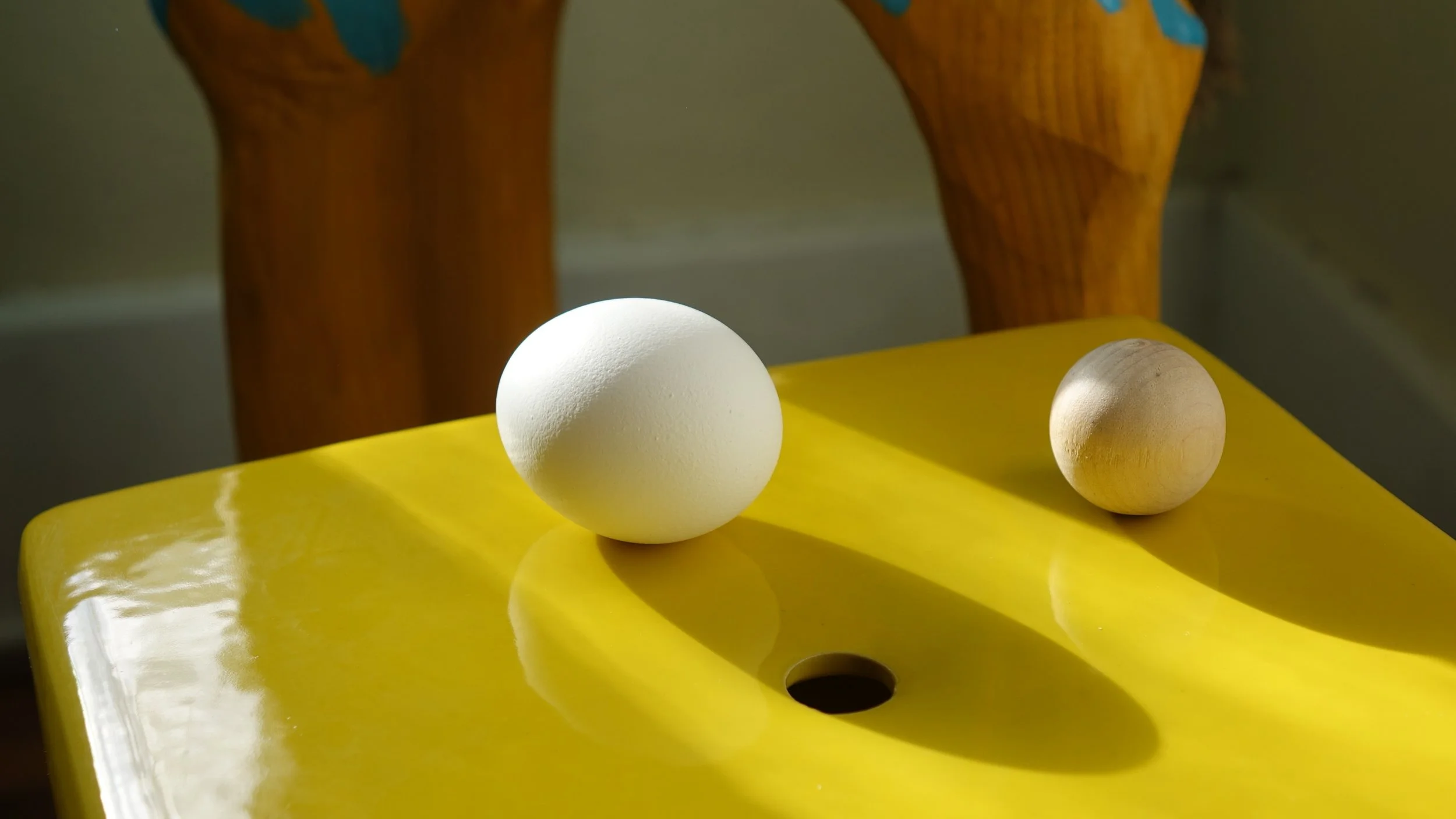
The first thing we’re going to try and get right is the cube. Start out by creating a polygon cube and setting its scale to match that of the real life cube. Since the scene scale is in inches, a scale of “1” is equal to one real world inch. Ex: my cube was ¾ of an inch on each side, so the Maya cube scale (on x, y, and z) would be .75. Go ahead and move the pivot of the cube to its bottom and snap the object to the top of the default grid in Maya, which we’ll treat as the table or ground, so that the cube sits on top of the grid. Next, we need our cube reference image in the scene, so in the attribute editor of the RenderCamShape, under the Environment tab, click on the button that says “create” next to image plane. When the next window pops up, click on the manila folder and plug in the photo with the cube. This is the same as inputting an image plane to one of the orthogonal cameras, but will be bound to the RenderCam, so that every time you move the camera, the image will move with it. Make sure that under ImagePlaneShape in the Placement tab, you hit the “fit to resolution gate” button so that the image matches the resolution in your render settings and doesn’t stretch. Now that you have your image plane set up, make sure you’re looking through your RenderCam, and line up the placement of the 3D cube with that of the one in the image as best as possible by tumbling the RenderCam around. This will take a lot of wiggling, but the more accurate you get the camera placement now, the easier the following steps will be. Go ahead and create a ground plane and place it under the cube, we’ll need it to see shadows. Now you’re ready to light! Create a spotlight and move it around until the shading position of your 3D cube matches that of the cube in the photo. Make sure that the shadows cast by both cubes also match (again, just the position, we’ll deal with color later). Depending on how sharp the cast shadow in your photo is or isn’t, you may need to soften the edges of the Maya shadow. You can do this by going to the attributes of the spotlight and, under the Arnold tab, change the radius of the shadow. The higher the radius, the softer the shadow. If you soften the shadow, you’ll also have to up the samples (the slider directly above radius) in order to make sure it doesn’t look grainy, or pixelated. Once you’ve got the light position of the cube as close as possible, do the same steps again but with the wood ball. Create a sphere, make sure it’s the right size (keep in mind that the scale of spheres is measured by the radius, not by the diameter) and is sitting on the ground plane, plug the correct photo into the RenderCam image plane, match the sphere position, and then match the lighting on the spheres. You most likely will have to go back and forth between the cube and the sphere to get the lighting correct, as it could look correct for one of the shapes but not actually be in the right place. To make it easier to switch between the two objects and photos, place each group in its own display layer, at the bottom of the channel box. This will make it easier to view only certain items at a time. Once you’ve got both of those to match as close as possible, do it one more time, but this time with your object! Go ahead and add a shader to your object as well. Since we’re rendering in Arnold, use the Arnold AiSurface Shader. For my egg, I gave it a slight off-white color and used an eggshell texture to create a bump map as well as a spec map, and then played with values of each until I got a realistic looking texture. If you have more than one main light source and more than one cast shadow, just repeat the process for each individual light. Once you’re finished with that, you’re done with the key light, for now, and ready to move onto fill and bounce color!
Chrome ball cut to be used for Skydome
The next step of the process is to utilize the chrome ball from the light integration kit; we’re going to use it to create our own sky dome that will give proper fill lighting and color to the object. Start out by bringing the chrome ball image into any piece of photo editing software like Photoshop, and crop the image to a square that just barely fits the chrome ball inside of it. Save that image as a new version. Back in Maya, create a sphere and scale it up until the rest of the scene fits inside of it. In the attribute editor, under the shape node and in the Arnold tab, make sure that the “casts shadows” box is unchecked. Assign a Maya surface shader (not an AiSurface!) to the sphere. In the out color of the shader, click on the checkered box, right click over the file button, and then select “create as projection.” Back in the attribute editor, plug in the newly cropped chrome ball image. Make sure under the projection type dropdown menu that it’s set to “ball.” Under the Camera Projection Attributes tab, assign RenderCam to “Link to Camera.” The majority of the new texture should look normal, except for a pinch on one side. You want to rotate around the projection, not the sphere!, until the pinch is at center frame of your RenderCam. Now you’ll do a similar thing to the ground plane. Assign a new Maya surface shader, follow the same steps to do another projection, and input the Blank Slate image (the one without the object). This time, instead of using the ball projection type, use the perspective projection type. Now in the RenderCam view, the ground plane texture should line up with any image plane you have attached to the camera. You can adjust how bright either of these are by going to their respective projection nodes in the attribute editor. Under the Color Balance tab, adjusting default color, color gain, and color offset will change how the projections affect the lighting.
Now that the main lighting is done, we’re going to get the scene set up for compositing. This means we’ll be using lots of render layers. At the bottom of the channel box where the display layers are, there should be another tab called render. If not, go back to preferences (Windows > settings/preferences > preferences), then under the rendering category, choose “legacy render layers” in the dropdown menu of “preferred render setup system. If you have to do this, save out Maya and restart it, and the render layers tab should be there the next time you open your file. Maya automatically starts out with a masterLayer that contains everything and affects the settings of all the other render layers, unless you tell those layers otherwise. You’re going to start by creating a Beauty layer (use the polygon with a plus button to create a new empty layer). In the masterLayer, select everything, right click over the Beauty layer and selected “Add selected objects.” Right now both layers will render out the same image. What we want from the beauty layer is just the egg, without any of the background elements but with the proper lighting. We’ll do this by selecting the ground plane and going to the shape node in the attribute editor. Under the Arnold tab, right click on primary visibility and select “create layer override”, and then unselect that box. The layer override means that the settings won’t change in any layer but this one, and turning off primary visibility means that the ground plane will still affect the lighting in the scene without the ground plane itself rendering. Do the same thing for the sky dome. Now when you render, the only thing that should show up is the egg.
Now you’ll create the Shadow render layer. In this layer, you’ll only need to add the object, the ground plane, and the key light(s). In this layer, assign a new shader to the ground plane; don’t worry, shaders automatically come with layer override, meaning that this won’t affect the shaders in any other render layer. Use the Ai shadow matte shader; this will enable you to render out the shadow separately so that you can composite your image together properly later. You want the primary visibility to be on for the ground plane and off for the egg in this layer; don’t forget to use layer overrides. In the shadow matte shader, change the shadow color so that you can see it against the black background; the color you choose won’t affect the final result, it just makes it easier to find. If you have multiple shadows and key lights, make a separate shadow render layer for each one, just follow this process for each individual light.
Your next render layer will be Ground Occlusion. For this layer, only include the egg and the ground plane. Add the Ai Ambient Occlusion shader to both objects. Using layer overrides, turn primary visibility off for the object and on for the ground plane. Under the Ambient Occlusion shader, switch the white and black values so that the render looks inverted, this will make it easier to grab the alpha channel in Nuke later. Also in the shader, play with the spread and falloff sliders until you get something you like; don’t worry too much about it now, you probably won’t know what you’ll need until after you start to composite. Do make sure that you turn up the samples under the shader to get rid of any grain in the render caused specifically because of the ambient occlusion.
In my particular image, I also had a reflection that I needed to try and match. If you also have reflections, you’ll go ahead and create two more render layers: name on Ground Reflection, and one Ground Reflection Mask. Add everything from the Beauty layer to the Ground Reflection layer. Assign a new Ai standardsurface shader to the ground plane. Make this shader reflective by turning down or turning off the weight of the base color and turning the IOR of the specular color up. If you turn the base color completely off, the ground plane will be completely reflective, but in my case I needed a little of that yellow color in the reflection. I also didn’t want the surface to be completely smooth, so I added a bump map, using the Noise procedural to create some surface turbulence. For this layer, turn the primary visibility off for everything but the ground plane (and the lights, they won’t affect anything if primary visibility is turned off). In the Ground Reflection Mask layer, just add the egg and the ground plane. Add a Maya surface shader to the egg and make the color bright and easy to see.
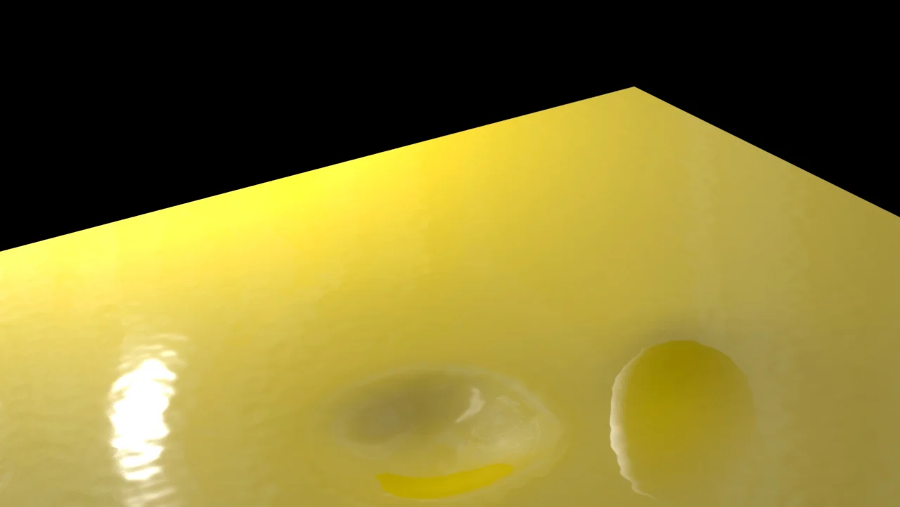
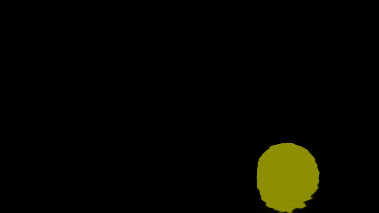
The last render layer that I created was a Sub Surface Scattering Render layer. You’ll only need this if your object is translucent. Since I was matching an egg, I definitely needed it. In this layer you’ll only need the egg and the key light. Create a new AiStandard Surface shader for the egg and turn the base weight off. Under the subsurface tab, turn the weight up all the way and assign a color to the SubSurface Color, similar to the actual color of the object. In radius, give it a color that matches what the insides of the object would be. For an egg, it’s a yellow-orange for the yolk. Then, play with the scale slider until you get something that matches your actual object. Again, you may have to come back and play with this later after you start compositing and find out what you need. Now you’re ready to render and start compositing!


We’re going to do a render sequence so we can render all our layers at once, so to get ready for that open the render settings. Where it says file name prefix, right click and select insert scene name, type “/”, and then right click again and select insert layer name. It should look like <Scene>/<RenderLayer>. This is a good way to keep track of exactly what each rendered image is. Set the image format to exr and the compression to none. Make sure the box “Merge AOVs” is checked. For Frame/Animation ext:, set it to name.#.ext. Under frame range, all three boxes should be “1.” The renderable camera should be set to RenderCam. The image size should be at whatever ratio you set it at the beginning, when you were matching the camera resolution. That’s all for the common tab. Under the Arnold tab, set the sampling levels to whatever you need them to be to get rid of any grain in the renders. You can also do layer overrides for these, just like with the primary visibility. For me, the only layer that had any different sample numbers was the subsurface scattering layer, where I turned the SSS samples up a lot. In the AOVs tab, and the reason for checking that Merge AOVs box earlier, we’re going to create an AOV for z depth. This means that along with the normal RGBA channels that images have, the renders will also have a depth channel, which can be used to create depth of field. In the box that reads “Available AOVs, scroll down and select “Z” which should move over to “Active AOVs”. Now you’re ready to render! Make sure your project is set and then choose the Rendering menu set. Under the Render drop down menu, click the box next to render sequence. Make sure the current camera is set to RenderCam and double check that the output file location is where you want it by clicking the manila folder. Also make sure that the box labeled “all render-enabled layers” is checked. When finished, click “Render Sequence and Close” and Maya will finish the rest of the rendering work! You will probably be returning to Maya later to make tweaks to some of the settings, but otherwise we’re ready to move onto Nuke and start compositing!
In Nuke, we’re going to start by reading all our images in. You can drag and drop all the files in, or press tab and type “read” and then read the images in. You will need all the images from your Maya render sequence: Beauty, Shadow, Occlusion Ground, Ground Reflection, Ground Reflection Mask, and Subsurface Scattering. You will also need the Clean Plate photo, the one without the object in it. While this isn’t for the composite image itself, you should also read in the photo with the object in it so you can compare the two while working. If you hit the “1” key whenever you select one of the images, it will show up in the viewer above the node tree. We’ll use the clean plate photo as the base and add things onto that. Now, since the clean plate photo is the original resolution but the renders are all smaller, the first thing to do is to reformat the clean plate photo to match the others. Hit tab and type reformat, double clicking on the option when it shows up. Connect the arrow from the clean plate to the reformat node, and in the output format select the correct resolution. If your resolution isn’t there, choose custom and set it yourself.
The next thing we’ll do is add the shadow to the background image. Add a color correct node (hit tab, type color correct) after the reformat node. Double click and play with the gain slider. This is how you’ll get the CG shadow to match the real one. Right now, this affects the whole image, so you need to use the shadow render layer as a mask. On the side of the color correct node is an arrow that when you drag out reads “Mask”. Connect that to the shadow render. Now you have a shadow! Just play with the color correct node settings until you get something that matches.
Now add the beauty render of the object to the composite. You can do this by creating a merge node and connecting the beauty layer to the clean plate. Merge can give a lot of different results based on the operation you assign to it, kind of like blending modes in Photoshop. For this particular merge, we want the egg over the clean plate, so the operation type is “over”, with the egg as input A and the background as input B, i.e. A over B or Egg over Background.
The shadow isn’t quite dark enough at the contact point of the egg, so next add the ground occlusion layer to the mix. The first thing you need to do is to make the ground occlusion layer an alpha layer instead of RGB, so add a shuffle node to it. I used this site, http://erwanleroy.com/nuke-for-beginners-the-shuffle-node/, to understand the shuffle node better. It even has a game you can use to practice! Essentially, you want the image to use the red channel as the alpha channel, so select the box where those two intersect, the bottom left. Now the occlusion layer will work like the shadow layer did, which worked the way it did because of the shadow matte shader. Now you’ll do the same thing you did with the main shadow and use the occlusion render as a mask for a color correct node. Add this node in between the last color correct node and the merge over node; the egg or other object needs to be on top of everything else, so all nodes feeding into the composite will be between that one and the clean plate. Now the issue is that the occlusion layer is shading everything around the egg, and not just adding to the already-established shadow. To fix that, make another merge node between the shadow render layer and the occlusion layer (put it after the shuffle though). The operation for this one will be in instead of over, because you want the occlusion layer in the shadow layer. Now you can play with the color correct settings until it matches the original object. You can also use this layer to create some extra bounce light off of the egg and onto the ground by doing another merge node, this time out, so that the occlusion is only on the outside of the shadow layer. Use that as a mask for another color correct node and play with the values to make it look like bounce light.
First Pass Render from Nuke
Now we’ll add the reflection layers. You have to do another shuffle node on the ground reflection mask to change the red channel to alpha. Once that’s done, merge the ground reflection render “in” the ground reflection mask render. This means that the reflection of the sky dome won’t show up in the final render because the mask is essentially blocking it out. Then, feed that Merge node into another color correct node so you have the ability to change the color and saturation of the reflection. Finally, connect the reflection through the color correct node into the main image pathway with another merge node. This one doesn’t have to have any specific operation, but can be whatever works the best for what you need. For my project, this was a screen merge node.
Next, we’ll add depth of field to the egg. In between the beauty render and the merge over node into the main image pathway, add a zdefocus node. A dot labeled “focal point” should show up somewhere in the viewer. Drag this over to the front of the object, to the area you want in focus. In this node, the math should be the direct type. For this, you can switch the output mode between result and focal plane setup in order to more easily see what you’re doing. While in focal plane setup mode, the object will be covered in a color or colors. Sections covered in green are in focus, sections in red are out of focus in front, and sections in blue are out of focus behind. Change the depth of field slider/number of the node in order to change the focus of the object; you can also change size and maximum. Play with these until you get something that matches the real photo.
Of the renders we initially put in, we only have the subsurface scattering left! Like the z depth, this will also be fed into the beauty render instead of the main image pathway. First, feed it into a color correct node so that you can change it however you need to. Then you feed that and the beauty layer into a merge node. For this merge, it ended up being beauty as A, subsurface scattering as B, and the merge type is screen. You can switch the order and the merge type to get the results you need. That merge was fed into the zdefocus because you also want the depth of field on the subsurface.
Nuke Node Tree for the First Pass Render
That’s it for the main render passes! Unfortunately for me, this ended up not yielding quite what I needed, meaning that I had to go back into Maya and change things and add more render layers, and add some more nodes into Nuke. All of these are specific to my project, but I’ll go over them as well.
I added a color correct node to the beauty render pass so that I could affect the color of the egg. When I added it though, it changed the whole image instead of just the egg, so I had to add a mask layer. I did this by reading in a copy of the beauty render, putting a shuffle node to switch it from RGB to alpha, and then fed that in as the mask for the color correct.
I wasn’t getting enough bounce light from the right side of the screen (in the environment, there was a bright, white wall out of frame that it directed a lot of lot back onto the egg), so back in Maya I added another light. I ended up using an area light, though a directional would also work fine. If you’re not planning on animating, then a spotlight works great, but otherwise one of the other two is easier as it doesn’t need to track with the object in order to light it evenly throughout the animation. I put this light in the beauty and ground reflection layers, as these are the only ones it really needs to affect.
The edges of my shadow didn’t quite match the reference, so I changed that as well. For this issue, you can go back into Maya and play with the radius until you get the result you need. For mine, the difference was so slight that I just threw a blur node onto the shadow render to make the whole thing slightly fuzzier. I put this node in between the shadow render and anything it was plugged into.
The contact shadow of my egg wasn’t dark enough, so I went back into Maya and added a new render layer with the same objects as the original ambient occlusion layer. I created a new ambient occlusion shader to the objects and played with the values until I got what I wanted; it ended up being a smaller, denser shadow at the base. I rendered it out and read it back into Nuke. Instead of replacing the other one, I used it in conjunction. I followed the same steps as I did for the other ground occlusion layer, putting a shuffle node on it and a merge in node into the shadow, which then fed into a color correct node.
The bottom of my egg also wasn’t dark enough, so like what I did with the shadow, I added an ambient occlusion pass to the egg. In Maya, I added another render layer for the object occlusion. I included the ground plane and object, just like for the others, and created a third ambient occlusion shader for them. For this layer though, create a layer override and turn primary visibility off for the ground plane and on for the egg. Once back in Nuke, add a shuffle node to turn the rgb values to alpha, and use it as a mask for a color correct. The Merge node from the beauty and subsurface passes will feed into this color correct, which will then feed into the zdefocus node.
I added a transform node to the original ground occlusion render to really get the positioning where I wanted it. I didn’t want the occlusion evenly across the shadow as it was darker in a certain area.
There was in issue at the edge of my egg, which had formed a weird, dark outline. This was most likely being caused by premultiplication, which you can read about here: http://www.spherevfx.com/written-training/miscellaneous-written-training/understanding-premultiplied-images/. Essentially it means that if you’ve been layering a lot of images with alphas together, that the pixels at the edge of the alpha start to become more opaque, creating an outline. Luckily, the fix for my problem was simple: I created a copy node, and everything that originally had gone into the zdefocus node went into the “B” feed on the copy node. A copy of the beauty layer of the egg fed into the “A” arrow, and the then the whole thing went into the zdefocus node, and the line disappeared!
Nuke Tree for final image pass
Lastly, I had a double shadow issue, where the color correct shadow overlapped with a shadow from the clean plate, stepping up the darkness even more and making the egg shadow composite uneven. To fix this, I added a roto node, which is essentially the same thing as a mask in after effects or the functioning of the pen tool but abilities of the lasso from Photoshop. With this, I drew a shape around the area I needed to lighten up. I then used a merge node to merge the roto into the shadow shape so that I didn’t have to worry about affecting the background color. I used all of that as the mask to another color correct node, and played with it until the roto color matched the other shadow color. Lastly, I used the feathering in the node to try and blend the new color correct into the original shadow color correct. This mostly worked, but still left a dark line at their border. To fix this, I added another roto node around the border between the other two, merged that into the blur from the shadow, and used it as a mask for another color correct node. I played with the feathering of the roto again, and got the problem to all but disappear.
When you’re ready to render out an image, attach a write node to the very end of your node tree. Under file, choose where you want to write it out and name it. When you name it, make sure you add the file extension at the end, of whatever kind you want, otherwise it may not render out properly. This is especially true with videos. Once you add the file extension, Nuke should fill all the other information out for you; double check that the file type is correct, and that the quality is up all the way. Hit the render button and choose the frame range (for just an image, 1-1, is the correct range). Select okay and your image will render! That’s all for the image! Here’s how mine turned out:
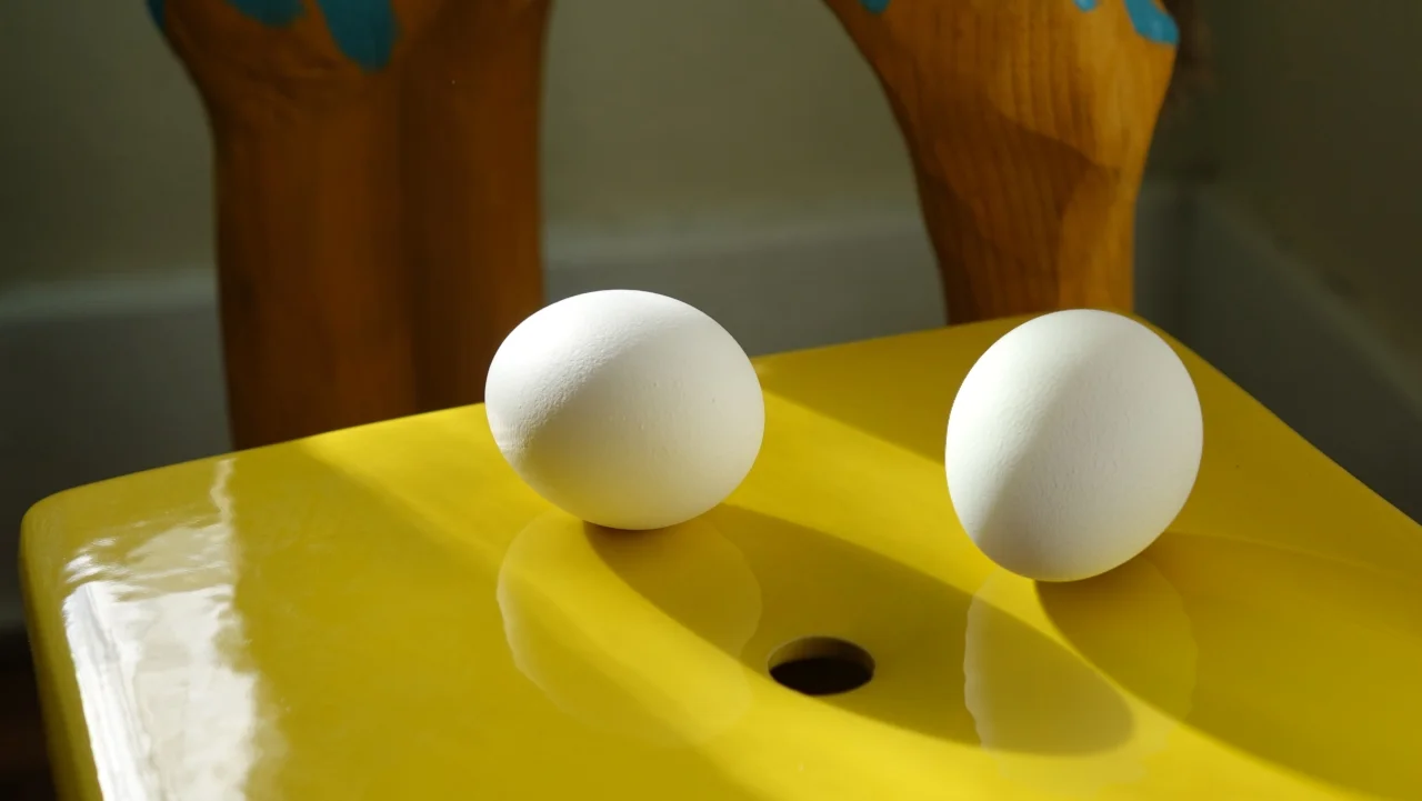
Final Pass Render from Nuke
Now that I got a still rendered out that I really liked, I went ahead and animated my object! The best test of if you did a good job compositing is if it still fits in the scene when it’s moving! Any animation is fine, I’m more of a character animator, so I did something more in my realm of interest, but affects, object physics, and cloth animation would work as well. It also doesn’t have to be super long, just a little test; mine was 5 seconds. The render will take a lot long this time around, but you’ll still set it up the same way.
Once I was done with the animation, I did test renders and found that I had some new issues crop up! One, the shadow in the photo that caused the issue with the egg’s shadow should technically have been shading the egg for part of the animation. Two, the egg shadow overlapped the shadow from the other egg, and also went off the side of the table it was sitting on. Three, the egg reflection also went off the side of the table, floating in space.
Nuke Tree for final Render
To fix the first problem, I created a plane and used it to block some of the light from reaching the egg at the right time. Just like at the beginning with the cube, I used the original photo to line up the CG shadow with the photo shadow.
For every other issue, I had to add new roto nodes. The first one I made was for the shadow. I drew a shape around the area where I wanted the shadow to be visible, not where I wanted to block it. That meant drawing around the edge of the table and the edge of the other egg’s shadow, so that my egg’s shadow wouldn’t go off the edge or into that shadow. The “bg” arrow from the roto I attached to the original blank slate photo. I then used a merge node to merge the egg shadow into the new roto (shadow as A, roto as B, and merge type as in), and fed that node into the shadow blur node. I did a similar thing for the reflection, drawing a roto around the area I wanted the reflection to stay inside, using the clean plate as the BG. I added another merge node, the reflection and reflection mask merge node feeding into A with roto as B and the merge type as in. That fed into the reflection color correct node. With that, my animation was done, and everything was looking great! I used the write node again, but this time used a video format extension, like mov. Make sure the file type and fps (frames per second) are correct, and hit render. This time, make sure that the frame range is as long as your animation. Ex: mine was 5 seconds long at 24 fps, so the frame range was 1-120. Hit okay, and you’ll have your fully composited video render finished in a few minutes! This is how my video ended up: